
 |  |  |  |  |  |
| ELECTRICAL |
Hello and welcome back aboard! This time, following up our last tutorial about natural moonlight, we will be discussing a very 'CGI-traditional' fashion of illumination: electrical lighting. Although this kind of light is considered 'artificial' we will learn later on that it has a very natural background (at least as long as we stay with a tungsten light, which we propose in this tutorial). So, why 'CGI-traditional' you might ask? Well, ever since there is CGI (computer generated imaging), tungsten bulbs have been a very 'easy' to simulate type of lightsource, for mathematical reasons. The classic tungsten bulb has a relatively limited area of light emission, which, in the 3d/simulation world, can be simplified down believably to an infinitesimal point - the classic point-light (as a side note, its little brother, the spot-light, is nothing but a point-light with more sohpisticated features). In the past of CGI this infinitesimal (infinitely small) point made it possible to render 3d images effectively and fast, due to a logic reason: To simulate a lightsource, we basically need three points for the math, i.e. the position of the 'eye' of the observer, the point on the surface thats being lit, called the 'intersection point', and the position of the lightsource - all these together mathematically make out the rendering, and since an infinitesimal point is obviously the most simple element in 3d space, it can be computed with very little expense in this context - and even more important, it converges noise-free per se, since the point is strictly determined. Back in the times when computers werent as high-clocked as today this was crucial, and point-light based lighting was mandatory, along with closely related techniques as spot-lights and directional-lights (which uses an infinitely far away point instead). So for CGI the point light was pretty much as important as Edison's light bulb for real life. Computer lightsources have evolved since then however, just as the real bulb did, and still (for both!) the principles have stayed the same. And still the most believable deployment of a point lights is at the simulation of a tungsten bulb. Enow with the history though, let's have a closer look at how tungsten bulbs actually work and why they look as they look. This is, as always, the essential starting point when trying to simulate a specific case. The operation of a usual incandescent bulb is quite simple: an electric current is passed through a tungsten (also called wolfram) filament, which is enclosed by a glass bulb that contains a low pressure inert gas, to avoid oxidation of the electrically heated filament. Depending on the type of the filament, the operation heat is typically between 2000 and 3300 degree Kelvin (around 3140 to 5480 degree Fahrenheit, or 1727 to 3027 degree Celsius). This thermal increase induces radiation (also, but not only) in the human visible light spectrum, in the form of a so called 'black body'. The interesting thing about this black body (which actually is an idealized physical model of a radiator/light emitting body) is that its emitted spectrum, i.e. the color, can be estimated by solely knowing the (absolute) temperature of the black body, according to Planck's Law. Inversedly, one application of this is in astrophysics, where scientists can measure the temperature of a star by analyzing its spectrum. And furthermore, this way the movement of stars and galaxies can be determined, if this estimated spectrum is shifted either towards blue (getting closer) or red (moving away), due to the electromagnetic equivalent of the sonic Doppler-effect, called redshift or Hubble-effect. Well, this all means we have a (at least theoretically) strictly defined spectrum, or color in our case, for a glowing tungsten bulb. This color lies on the so called Planckian locus (Fig. 1), a coordinate in a particular color space, and ranges, for our needs, from the visible red, over white to blue. There is several black-body-Kelvin-temperature-to-color converters on the internet, but fortunately there is a standard tool that ships with mental ray, which makes our life a bit easier. |
|


It's called, guess what, mib_blackbody and can be found in Maya under the 'mental ray lights' tab in the hypershade (Fig. 2). This utility outputs the desired color, according to the temperature we feed it. |
|

So let's model the actual light. To deliberately break with the tradition I decided to use a spherical area light (instead of the good ol' point light), placed closely to the center of the actual bulb geometry, so that it's encompassed by it (Fig. 3). |
|

Obviously, if we rendered it this way, we would face trouble due to the occlusion caused by the bulb geometry. Theres several ways to come around this - we could either adjust the bulb's glass shader, so it handles the transparency, though we have to increase the ray depths accordingly. Or, and that's a bit smarter in this case, because we wouldnt have to mess with the ray depths, we simply exclude the bulb from shadow and reflection/refraction tracing by setting some flags in the object's shape node (Fig. 4). Since the bulb is 'incandescent' anyway we can neglect its shadow. |
|

To give our light the desired color, I simply create the mib_blackbody node and connect it to the area light's color slot (Fig. 5). |
|

I also set its decay rate to 'quadratic' - this is very important to give it a natural falloff and to obey physical rules. The intensity is left at 1.0, I completely hand this over to the mib_blackbody, where I also set a reasonable temperature for our tungsten filament (something between 2000 and 3300, I decided for 3000 degree Kelvin) (Fig. 6). I repeat all this steps for the second bulb, except that I used the same mib_blackbody node for its color, just to speed up the workflow a bit, as we assume that both bulbs are of the same type. |
|

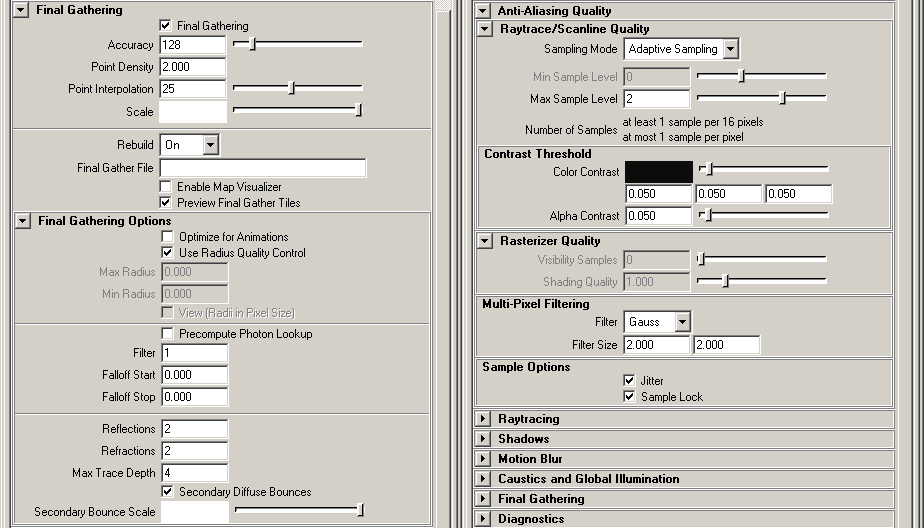
We're pretty much ready to render now. Before we push the button though, let's adjust the render globals to something more reasonable. The raytracing depths for example are not quite what we need, although they only need little change (Fig. 7). |
|

I'm also switching on final gathering for the indirect light contribution. I set the accuracy, point density and trace depths to a good-to-play-with value, we shall change these for the final render of course later on (Fig. 8). |
|

Because the final gathering diffuse bounces setting have a little shortcoming in Maya 8.5, I set them in the actually controlling node, which is called miDefaultOptions (type 'select miDefaultOptions' without the quotes into the MEL command line to bring it up in the attribute editor) (Fig. 9). |
|

Last but most important, I put ourselves into the right color space, which is sRGB, the commonly used space for things like photographs. Although we cannot precisely apply this color profile right away (at least not easily in mental ray for Maya 8.5), we simply apply a so called gamma correction curve of value 2.2 to our image, which usually is sufficient. This implies some caution: because the textures we usually use are already in sRGB, or hence gamma corrected, we need to un-gamma them before we correct the whole image again. That seems awkward and unnecessary but makes total sense for a reason - if we want the (gamma corrected/sRGB) texture to look like we are used it to look like, we need to remove the gamma correction first, before we RE-apply it on the whole image. Odd stuff, but makes our picture look pretty and more natural. Thankfully mental ray has this remove-texture-gamma-and-re-apply-it thing built in already, and we simply set the desired gamma correction value in the framebuffer>primary framebuffer tab of the render globals (Fig10). However, mental ray wants us to actually specify the inverted function, which is 1/2.2=0.455 in our case. For more information on the gamma issue, I encourage you to read the 'Note on Color Space' in the very first part of this tutorial series. |
|

Well, here's our first test rendering with the settings above (Fig11). Straaange things happening, I know. |
|

The reason for this is the very close proximity of geometry to our area light - the final gathering usually goes nuts on this. There's a cheap solution to this, we simply set the final gathering filter to greater than 0, I decided for 1 which usually does a good enough job (Fig12). Usually it is desirable to completely avoid this filter (i.e. leave it at 0), because it introduces strange bias in some situations, e.g. if we lit our scene completely by HDRIs. So use it wisely, or only if you are forced to, like in our case. If you are still encountering artifacts, exclude the lamp guard and basement as well from the reflection/refraction tracing. |

Let's see if it helped, and yep, that looks much better (Fig13). |
|

I'm preparing for the final rendering now, by upping the general anti aliasing quality. The final gathering needs some lifting too (Fig14). |
|
Here we go (Fig15). |
|

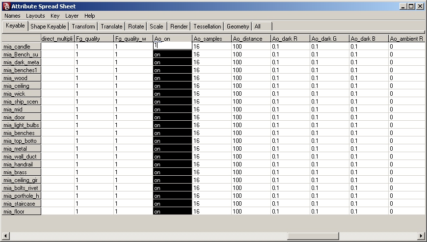
The last thing I added was the mia_material's built-in detail ambient occlusion, by selecting all the mia_materials and change the Ao_on attribute to 1 (ON) in the attribute spread sheet (Fig16). This reveals little details without hammering the wellknown and usually way too strong ambient occlusion corner-darkness onto our image. |
|
Also, I decided to render to a higher fidelity fancy super duper 32bit framebuffer - simply because everyone does..! No seriously, at least for stills it's better of course to render to a floating point format. After all this gives us a more peaceful sleep while the renderer works over night. However, for reasons of efficieny I decided for a 16bit half framebuffer, which is still a floating point format but less space-/bandwith-eating. To use this, the only possible fileformat for now is OpenEXR - that's not a bad thing, since OpenEXR is quite fancy (for real!) (Fig17). |
|

After touching some contrasts and colors here and there I came up with my final interpretation (Fig18). I hope you enjoyed following this little tutorial about electric light, and be with us next time with the candle light session! |
|
Credits: Original concept and geometry - Richard Tilbury Original idea - Tom Greenway Editor - Chris Perrins Tutorial - floze |

| | | | | |
i dont get it. i am familiar with FG, raytracing ...
ReplyDeletein my test scene i must raise the intensity value very high to have enough light so the wall is over lighted ,and the temperature of 3200 makes my scene red.
you have to crank the intensity up to compete with the quadratic decay on the lights.
ReplyDeleteset the intensity on the mib_blackbody1 to 2500 like the image in the tutorial
Hello, sorry for my English. I try with the tutorial, but the result is an overexposed scene: http://img130.imageshack.us/i/roommental.jpg/
ReplyDeleteI do not understand what the problem is. I´m lost, all the steps are ok. I am grateful for your help. Thank you.
Hi great tuts top notch stuff -
ReplyDeleteI was wondering in maya the only thing that you have to do 2 render out non linear is...
-have your gamma set to 0.455 in the frambuffer
-Render out to a RGBA(float) 4x32bit or rgba (half)4X16bit
-and have your image formate to open EXR
do i have the steps correct?
also why on your filter do you use a Mitchell or gauss and then turn your filter size to 2 instead of the default 4 or 3
Thanks a bunch for your help
~J
They accept adaptors with sockets which you can insert anywhere along a linear slot in its surface. And they make a range of configurations besides the wall mount we see here.Home Safety Inspection Services
ReplyDeletealso why on your filter do you use a Mitchell or gauss and then turn your filter size to 2 instead
ReplyDeleteThanks a bunch for your help
www.plumbingdallastxpro.com